Reference 1: Basic Structures
Few things are harder to put up with than the annoyance of a good example.
Mark Twain, Pudd’nhead Wilson, 1894
Every data model is composed of the same basic structures. This is a major advantage because you can focus on a small part of a full data model without being concerned about the rest of it. As a result, translation to a relational database is very easy because you systematically translate each basic structure. This reference describes each of the basic structures and shows how they are mapped to a relational database. Because the mapping is shown as a diagram and SQL CREATE statements, you might use this section frequently when first learning data modeling.
One entity
No relationships
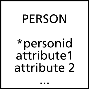
The unrelated entity was introduced in Chapter 3. This is simply a flat file, and the mapping is very simple. Although it is unlikely that you will have a data model with a single entity, it is covered for completeness.
A 1:1 recursive relationship
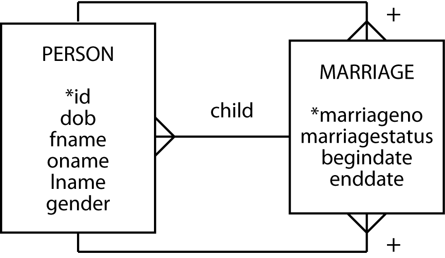
A recursive one-to-one (1:1) relationship is used to describe situations
like current marriage. In most countries, a person can legally have zero
or one current spouse. The relationship should be labeled to avoid
misunderstandings. Mapping to the relational database requires that the
identifier of the one end of the relationship becomes a foreign key. It
does not matter which one you select. Notice that when personid is
used as a foreign key, it must be given a different column name—in
this case partner—because two columns in the same table cannot have
the same name. The foreign key constraint is not defined, because this
constraint cannot refer to the table being created.

A recursive 1:m relationship
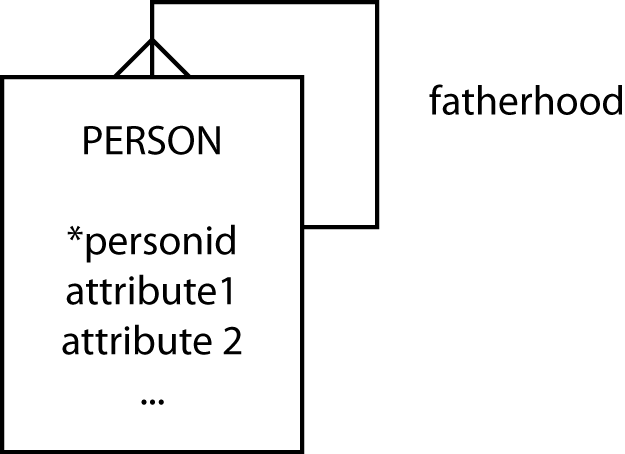
A recursive one-to-many (1:m) relationship describes situations like fatherhood or motherhood. The following figure maps fatherhood. A father may have many biological children, but a child has only one biological father. The relationship is mapped like any other 1:m relationship. The identifier of the one end becomes a foreign key in the many end. Again, we must rename the identifier when it becomes a foreign key in the same table. Also, as before the foreign key constraint is not defined because it cannot refer to the table being created.
CREATE TABLE person (
    personid    INTEGER,
    Attribute1  … ,
    Attribute2  … ,
    …
    father      INTEGER,
        PRIMARY KEY(personid));
It is possible to have more than one 1:m recursive relationship. For
example, details of a mother-child relationship would be represented in
the same manner and result in the data model having a second 1:m
recursive relationship. The mapping to the relational model would result
in an additional column to contain a foreign key mother, the
personid of a person’s mother.
A recursive m:m relationship
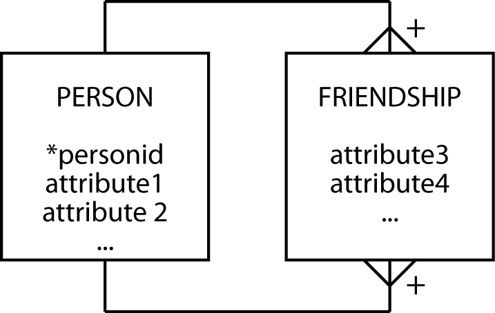
A recursive many-to-many (m:m) relationship can describe a situation such as friendship. A person can have many friends and be a friend to many persons. As with m:m relationships between a pair of entities, we convert this relationship to two 1:m relationships and create an associative entity.
The resulting entity friendship has a composite primary key based on the
identifier of person, which in effect means the two components are based
on personid. To distinguish between them, the columns are called
personid1 and personid2, so you can think of friendship as a pair of
personids. You will see the same pattern occurring with other m:m
recursive relationships. Notice both person identifiers are independent
foreign keys, because they are used to map the two 1:m relationships
between person and friendship.
CREATE TABLE friendship (
    personid1   INTEGER,
    personid2   INTEGER,
    attribute3  … ,
    attribute4  … ,
    …
        PRIMARY KEY(personid1,personid2),
        CONSTRAINT fk_friendship_person1
            FOREIGN KEY(personid1) REFERENCES person(personid),
        CONSTRAINT fk_friendship_person2
            FOREIGN KEY(personid2) REFERENCES person(personid));
A single entity can have multiple m:m recursive relationships. Relationships such as enmity (not enemyship) and siblinghood are m:m recursive on person. The approach to recording these relationships is the same as that outlined previously.
Two entities
No relationship
When there is no relationship between two entities, the client has decided there is no need to record a relationship between the two entities. When you are reading the data model with the client, be sure that you check whether this assumption is correct both now and for the foreseeable future. When there is no relationship between two entities, map them each as you would a single entity with no relationships.
A 1:1 relationship
A 1:1 relationship sometimes occurs in parallel with a 1:m relationship between two entities. It signifies some instances of an entity that have an additional role. For example, a department has many employees (the 1:m relationship), and a department has one boss (the 1:1). The data model fragment shown in the following figure represents the 1:1 relationship.
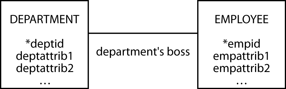
The guideline, as explained in Chapter 6, is to map the relationship to
the relational model by placing the foreign key at the mandatory
relationship side of the relationship. In this case, we place the
foreign key in department because each department must have an
employee who is the boss.
A 1:m relationship
The 1:m relationship is possibly the easiest to understand and map. The mapping to the relational model is very simple. The primary key of the “one” end becomes a foreign key in the “many” end.

An m:m relationship
An m:m relationship is transformed into two 1:m relationships. The mapping is then a twofold application of the 1:m rule.

The book and borrower tables must be created first because copy
contains foreign key constraints that refer to book and borrower.
The column borrowerid can be null because a book need not be borrowed;
if it’s sitting on the shelf, there is no borrower.
Another entity’s identifier as part of the identifier
Using one entity’s identifier as part of another entity’s identifier tends to cause the most problems for novice data modelers. One entity’s identifier is part of another identifier when there is a plus sign on an arc. The plus is almost always at the crow’s foot end of a 1:m relationship.
Tables are formed by applying the following rule: The primary key of the table at the other end of the relationship becomes both a foreign key and part of the primary key in the table at the plus end. The application of this rule is shown for several common data model fragments.
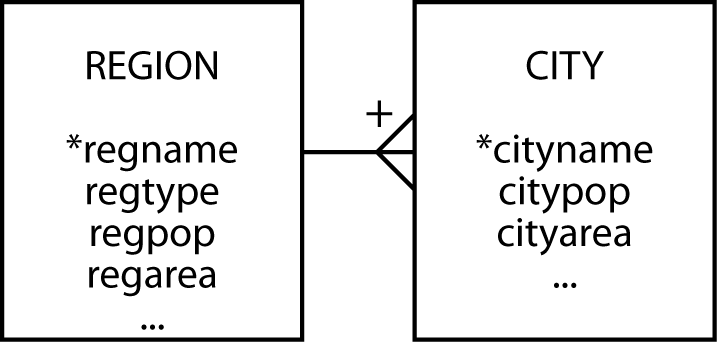
A weak or dependent entity
In the following figure, regname is part of the identifier (signified by the plus near the crow’s foot) and a foreign key of city (because of the 1:m between region and city).
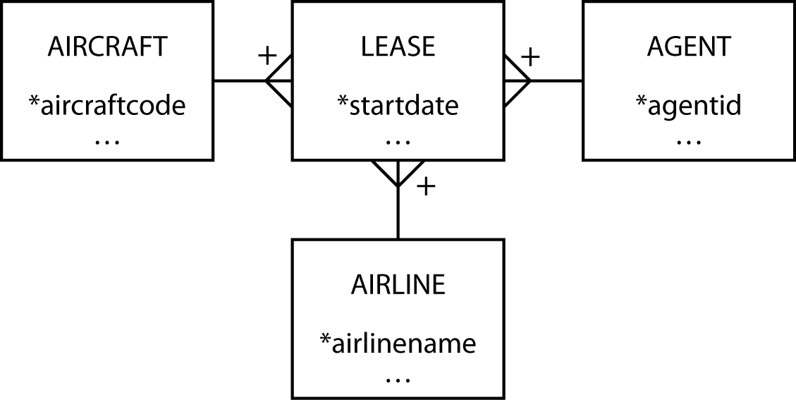
An associative entity
In the following figure, observe that cityname and firmname are both part of the primary key (signified by the plus near the crow’s foot) and foreign keys (because of the two 1:m relationships) of store.

A tree structure
The interesting feature of the following figure is the primary key. Notice that the primary key of a lower level of the tree is a composite of its partial identifier and the primary key of the immediate higher level. The primary key of department is a composite of deptname, divname, and firmname. Novice modelers often forget to make this translation.

CREATE TABLE division (
    divname     VARCHAR(15),
    …
    firmname    VARCHAR(15),
        PRIMARY KEY(firmname,divname),
        CONSTRAINT fk_division_firm
            FOREIGN KEY(firmname) REFERENCES firm(firmname));
CREATE TABLE department (
deptname VARCHAR(15),
…
divname VARCHAR(15),
firmname VARCHAR(15),
PRIMARY KEY(firmname,divname,deptname),
CONSTRAINT fk_department_division
FOREIGN KEY (firmname,divname)
REFERENCES division(firmname,divname));CREATE TABLE section (
sectionid VARCHAR(15),
…
divname VARCHAR(15),
firmname VARCHAR(15),
deptname VARCHAR(15),
PRIMARY KEY(firmname,divname,deptname,sectionid),
CONSTRAINT fk_department_department
FOREIGN KEY (firmname,divname,deptname)
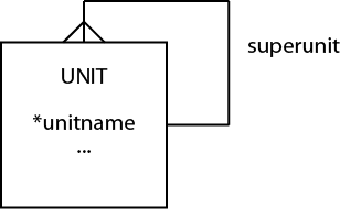
REFERENCES department(firmname,divname,deptname));Another approach to a tree structure
A more general approach to modeling a tree structure is to recognize that it is a series of 1:m recursive relationships. Thus, it can be modeled as follows. This model is identical in structure to that of recursive 1:m reviewed earlier in this chapter and converted to a table in the same manner. Notice that we label the relationship superunit, and this would be a good choice of name for the foreign key.